
The spanning tree protocol is a layer 2 protocol used to avoid loops in a switched network. In discussing the spanning tree protocol here, I will try to be as practical about it as possible. We will look at why you need the spanning tree protocol, one of the cases involving the spanning tree protocol, and how to manipulate the spanning tree root bridge selection process so that your preferred switch becomes the root bridge.
The use of spanning tree protocol: as I said earlier, STP was introduced primarily to help avoid loops on a network. Often times we design our networks for redundancy purposes. This is done so that the network stays up even if one of the switches fails. Unfortunately, such designs can cause loops in a switched network. To avoid this, STP was introduced. Therefore, if you do not have more than one switch on your network, you do not have to implement spanning tree.
How does STP work?
The Spanning Tree Protocol works by making one of the switches on the network the root bridge. The selection process is done using the switch priority and the mac address. If the switches have the same priority values, then the mac address will be used as the tie breaker. Once a root bridge has been selected, the switch with the highest priority value mac address will have one of its ports blocked. This is done to avoid a loop on the network.
How to influence the root bridge selection process.
Because by default all switches have default priority values of 32768 and all switch ports are placed in vlan1, the default priority value for Cisco catalyst switches for vlan1 is 32769. When two or more switches are tied by priority values, the switch with the lowest mac address becomes the root bridge. This is not good because the oldest switch is usually the one with the lowest mac addresses. The oldest switch on the LAN will definitely have the weakest processor and you do not want to the entire LAN traffics passed through it to the router. It may be unable to handle it. Faced with a situation like this, you need to lower the priority value of your preferred switch, assuming such development was considered in your topology design. Consider the topology below:

The design above has an issue because the wrong switch has been elected the root. Traffics from the hosts attached to switch A will go through Switch B to Switch C, making the link between Switch A and Switch B, as well as the link between Switch B and Switch C congested. A good design will be to make switch C the root bridge so that the link between Switch A and Switch B will be blocked. When this happens, internet-bound traffics from hosts on Switch A can go to the router through Switch C and Switch B can do same. First of all, let us find out which switch is the root bridge. It is obvious it is not switch C because a root bridge does not have a blocked port. So, it is between switch A and switch B. From the privilege mode of switch A, use the sh spanning-tree vlan 1 command.

From the output above, switch A is not the root bridge. How do I know this? Because the root mac address is not the same as the bridge mac address. The root mac address is the mac address of the switch that has been elected the root while the bridge mac address is the mac address of the switch you are logged into- switch A. Let’s check on switch B.

From the output, switch B is the root bridge for vlan 1. How do I know that switch B is the root bridge for vlan 1?
1. The mac address of the root bridge and the mac address of switch B are the same.
2. The message that reads ” this bridge is the root”
3. Allports on switch B that are parts of vlan 1 are in designated forwarding state.
How can we make switch C the root bridge?
By simply lowering the vlan 1 priority number on switch C to a number lower than those on Switch A and Switch B. We can do this in two ways:
Method 1
By typing the command spanning-tree vlan 1 root primary. This method assigns a priority value of 24576 to the switch. When you add this to the vlan number, in this case vlan 1, it becomes 24577. This method can only be effective provided there is not switch on that vlan with a priority value lower than that.
Method 2
Type the command spanning-tree vlan 1 priority 0. When the vlan number (ID) is added, e.g, vlan 1, the priority for vlan 1 becomes 1. Using this method requires that the priority value be entered in increment of 4096. This means that you can only enter numbers such as 0, 4096, 8192, till the highest value, which is 61440. Let’s use the second method to make switch C the root bridge for vlan 1.
SW-C(config)#sp vlan 1 priority 0
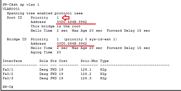
From the image above, the vlan 1 priority value for switch C is now 1. I set it to 0, so 0+1=1 (1 is the vlan number). the Mac address of switch C is now the same with the mac address of the root bridge with the message ” this bridge is the root” boldly displayed. All ports on switch C are now in designated forwarding state. See what the topology now looks like below:
