
If you are reading this post, it means you want to know how to implement Cisco l3 mpls for connecting customers with multiple branch offices. Multiprotocol Label Switching (MPLS) is an advanced routing tachnique used in telecommunication to route data between network nodes using label distribution protocols (LDP) instead of the conventional Internet Protocols (IP).
Implementing L3 MPLS requires the provisioning of at least a provider router, two or more provider edge (PE) routers, configuration of virtual routing and forwarding on PE routers, configuration of multiprotocol border routing protocol (mBGP) on provider edge routers to carry vpn4 traffics between customer branch offices, and configuration of dynamic routing protocol (in this case, ospf) on PE and customer edge (CE) routers.
Before going further, let me explain what P, PE, and CE routers are. Provider routers are routers owned and managed by the service provider. This routers have mpls enabled both globally and on all interfaces facing provider edge routers. However, they do not perticipate in vrf and mbgp.
Provider egde routers are the connecting points to mpls customers. In addition to having mpls enabled both globally and on interfaces connecting provider and other provider edge routers, a PE router participates in vrf and mbgp. It also serves as redistribution point between internal routing protocols run within a vrf and mbgp run between provider edge routers.
Also read: Cisco DMVPN setup for connecting branch offices, ATM and POS to HQ
CE stands for customer edge. The CE belongs to the customer and is used to connect to an mpls circuit. It can be provided, configured and managed by a service provider. In addition to having an assigned IP on the interface connecting to the service provider ( IP is provided by the ISP), it must be configured to run the same IGP with the connecting PE router.
Network Topology

Objective
In this lab, our objective is to implement l3 mpls to provide reachability between all offices of a customers with four branch offices spread across four states (PHC, LAG, KAN, and ABJ) in Nigeria. Our mpls circuit should provide redundancy in a way that each PE router has three label switching path (LSP) to reach each of our customer’s branch office.
IP address configuration
I will configure IP addresses on Provider and Provider edge routers using the addressing scheme on the network topology.
Core-P
core(config)#int g1/0

core(config-if)#ip add 1.1.1.9 255.255.255.252

core(config-if)#desc connection to KAN-PE

core(config-if)#no shut

core(config-if)#int g2/0

core(config-if)#ip add 1.1.1.17 255.255.255.252

core(config-if)#desc connection to ABJ-PE

core(config-if)#no shut

core(config-if)#int g3/0

core(config-if)#ip add 1.1.1.13 255.255.255.252

core(config-if)#desc connection to LAG-PE

core(config-if)#no shut

core(config-if)#int g4/0

core(config-if)#ip add 1.1.1.5 255.255.255.252

core(config-if)#desc connection to PHC-PE

core(config-if)#no shut

core(config-if)#int loopback0

core(config-if)#ip add 11.11.11.11 255.255.255.255
PHC-PE
PHC-PE(config)#int g1/0

PHC-PE(config-if)#ip add 1.1.1.6 255.255.255.252

PHC-PE(config-if)#desc connection to core-P

PHC-PE(config-if)#no shut

PHC-PE(config-if)#int g2/0

PHC-PE(config-if)#ip add 1.1.1.25 255.255.255.252

PHC-PE(config-if)#desc connection to LAG-PE

PHC-PE(config-if)#no shut

PHC-PE(config-if)#int g3/0

PHC-PE(config-if)#ip add 1.1.1.1 255.255.255.252

PHC-PE(config-if)#desc connection to KAN-PE

PHC-PE(config-if)#no shut

PHC-PE(config-if)#int g4/0

PHC-PE(config-if)#ip add 192.168.1.1 255.255.255.252

PHC-PE(config-if)#desc connection for PHC-CE vrf

PHC-PE(config-if)#no shut

PHC-PE(config-if)#int loopback0

PHC-PE(config-if)#ip add 2.2.2.2 255.255.255.255
LAG-PE
LAG-PE(config)#int g1/0

LAG-PE(config-if)#ip add 1.1.1.14 255.255.255.252

LAG-PE(config-if)#desc connection to core-P

LAG-PE(config-if)#no shut

LAG-PE(config-if)#int g2/0

LAG-PE(config-if)#ip add 1.1.1.26 255.255.255.252

LAG-PE(config-if)#desc connection to PHC-PE

LAG-PE(config-if)#no shut

LAG-PE(config-if)#int g3/0

LAG-PE(config-if)#ip add 1.1.1.21 255.255.255.252

LAG-PE(config-if)#desc connection to ABJ-PE

LAG-PE(config-if)#no shut

LAG-PE(config-if)#int g4/0

LAG-PE(config-if)#ip add 192.168.2.1 255.255.255.252

LAG-PE(config-if)#desc connection for LAG-CE vrf

LAG-PE(config-if)#no shut

LAG-PE(config-if)#int loopback0

LAG-PE(config-if)#ip add 3.3.3.3 255.255.255.255
KAN-PE
KAN-PE(config)#int g1/0

KAN-PE(config-if)#ip add 1.1.1.10 255.255.255.252

KAN-PE(config-if)#desc connection to core-P

KAN-PE(config-if)#no shut

KAN-PE(config-if)#int g2/0

KAN-PE(config-if)#ip add 1.1.1.2 255.255.255.252

KAN-PE(config-if)#desc connection to PHC-PE

KAN-PE(config-if)#no shut

KAN-PE(config-if)#int g3/0

KAN-PE(config-if)#ip add 1.1.1.29 255.255.255.252

KAN-PE(config-if)#desc connection to ABJ-PE

KAN-PE(config-if)#no shut

KAN-PE(config-if)#int g4/0

KAN-PE(config-if)#ip add 192.168.3.1 255.255.255.252

KAN-PE(config-if)#desc connection for KAN-CE vrf

KAN-PE(config-if)#no shut

KAN-PE(config-if)#int loopback0

KAN-PE(config-if)#ip add 4.4.4.4 255.255.255.255
ABJ-PE
ABJ-PE(config)#int g1/0

ABJ-PE(config-if)#ip add 1.1.1.18 255.255.255.252

ABJ-PE(config-if)#desc connection to core-P

ABJ-PE(config-if)#no shut

ABJ-PE(config-if)#int g2/0

ABJ-PE(config-if)#ip add 1.1.1.30 255.255.255.252

ABJ-PE(config-if)#desc connection to KAN-PE

ABJ-PE(config-if)#no shut

ABJ-PE(config-if)#int g3/0

ABJ-PE(config-if)#ip add 1.1.1.23 255.255.255.252

ABJ-PE(config-if)#desc connection to LAG-PE

ABJ-PE(config-if)#no shut

ABJ-PE(config-if)#int g4/0

ABJ-PE(config-if)#ip add 192.168.4.1 255.255.255.252

ABJ-PE(config-if)#desc connection for ABJ-CE vrf

ABJ-PE(config-if)#no shut

ABJ-PE(config-if)#int loopback0

ABJ-PE(config-if)#ip add 5.5.5.5 255.255.255.255
OSPF Configuration
The next step involves the configuration of ospf on P router and all PE routers to ensure full IPv4 reachability. This is needed to establish mpls ldp neighbor relationship among participating mpls routers.
Core-P
core-p(config)#router ospf 1

core-p(config-router)#netw 1.1.1.4 0.0.0.3 area 0

core-p(config-router)#netw 1.1.1.8 0.0.0.3 area 0

core-p(config-router)#netw 1.1.1.12 0.0.0.3 area 0

core-p(config-router)#netw 1.1.1.16 0.0.0.3 area 0

core-p(config-router)#netw 11.11.11.11 0.0.0.0 area 0

core-p(config-router)#no auto
PHC-PE
PHC-PE(config)#router ospf 1

PHC-PEconfig-router)#netw 1.1.1.0 0.0.0.3 area 0

PHC-PE(config-router)#netw 1.1.1.4 0.0.0.3 area 0

PHC-PE(config-router)#netw 1.1.1.24 0.0.0.3 area 0

PHC-PE(config-router)#netw 192.168.1.0 0.0.0.3 area 0

PHC-PE(config-router)#netw 2.2.2.2 0.0.0.0 area 0

PHC-PE(config-router)#no auto
LAG-PE
LAG-PE(config)#router ospf 1

LAG-PEconfig-router)#netw 1.1.1.12 0.0.0.3 area 0

LAG-PE(config-router)#netw 1.1.1.20 0.0.0.3 area 0

LAG-PE(config-router)#netw 1.1.1.24 0.0.0.3 area 0

LAG-PE(config-router)#netw 192.168.2.0 0.0.0.3 area 0

LAG-PE(config-router)#netw 3.3.3.3 0.0.0.0 area 0

LAG-PE(config-router)#no auto
KAN-PE
KAN-PE(config)#router ospf 1

KAN-PEconfig-router)#netw 1.1.1.0 0.0.0.3 area 0

KAN-PE(config-router)#netw 1.1.1.8 0.0.0.3 area 0

KAN-PE(config-router)#netw 1.1.1.28 0.0.0.3 area 0

KAN-PE(config-router)#netw 192.168.3.0 0.0.0.3 area 0

KAN-PE(config-router)#netw 4.4.4.4 0.0.0.0 area 0

KAN-PE(config-router)#no auto
ABJ-PE
ABJ-PE(config)#router ospf 1

ABJ-PEconfig-router)#netw 1.1.1.16 0.0.0.3 area 0

ABJ-PE(config-router)#netw 1.1.1.20 0.0.0.3 area 0

ABJ-PE(config-router)#netw 1.1.1.28 0.0.0.3 area 0

ABJ-PE(config-router)#netw 192.168.4.0 0.0.0.3 area 0

ABJ-PE(config-router)#netw 5.5.5.5 0.0.0.0 area 0

ABJ-PE(config-router)#no auto
At the point, we have reachability among all P and PE routers and we are set up for the next phase, which is enabling mpls globally and on participating interfaces on P and PE routers. MPLS should not be enabled on interfaces connecting to customer edge (CE) routers.
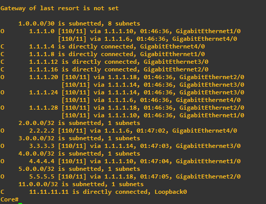
Using the sh ip route command on the Core-P router, we should see all ospf routes learned from our PE routers as shown below:
Because this post is too long already, I am going to stop here and continue in my next post. In that post, I will enable mpls and configure multiprotocol mgp.
You may like: Cisco layer2 mpls implementation made easy
Summary
To summarize, I will explain why the above configurations were entered.
First, we assigned IPs to all connecting interfaces on our P and PE routers as well as a loopback interface on each P and PE routers. While the IPs assigned to the physical interfaces are for reachabilities among our mpls routers, the looback interface IPs are for ldp neighborship establishment.
Ospf was configured to ensure that all mpls routers can reach one another. Without the configuration of a routing protocol (in this, ospf), mpls ldp (to be configured in part 2 of this post) can not be established.
Read the part2 of this post here.
By the way, if you are reading this post from outside Nigeria, PHC stands for Port Harcourt, the capital of Rivers State, LAG stands for Lagos, the commercial/entertainment capital of Nigeria, KAN is for Kano, the capital of Kano state, and ABJ is short for Abuja, the Federal Capital Territory of Nigeria.
If you enjoyed this tutorial, please subscribe to this blog to receive my posts via email. Also subscibe to my YouTube channel, like my Facebook page and follow me on Twitter.
2 thoughts on “How to implement Cisco L3 MPLS to connect four customer branches”